")
20 Yılı Aşan Tecrübe
Defne Mühendislik, 2005 yılında “mükemmeliyet merkezi” vizyonuyla kurulmuştur.
20 yılı aşan bilgi birikimimiz ve deneyimimizle, sürdürülebilir ve başarılı birçok projeyi hayata geçirdik. KOBİ’lerden büyük sanayi kuruluşlarına kadar geniş bir yelpazede çalışarak; ürün tasarımı, ürün geliştirme ve kalite kontrol süreçlerinde güvenilir bir mühendislik ortağı olduk.
Farklı sektörlerde gerçekleştirdiğimiz projeler sayesinde, derin uzmanlık ve gerçek bir fark yaratan tecrübeler edindik.
Gelin Birlikte Değer Katalım

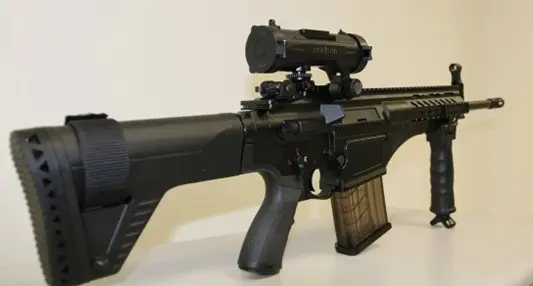
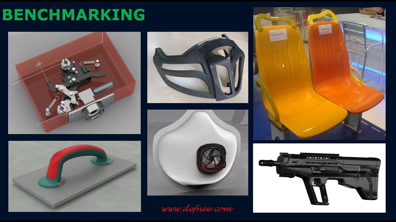
Kıyaslama ( Benchmarking ) Ürün Geliştirme ve Değer Mühendisliği proseslerinin kritik bir adımıdır. Genellikle bir işletmenin kendi performansını değerlendirebilmesi için, benzer veya daha yüksek performansı olan işletmeleri incelemesi, bu işletmelerin iş yapma usulleri ile kendininkini karşılaştırmasıdır. Günümzüde ürünlerin teknik özelliklerinin, performanslarının ve fiyatlarının karşılaştırılmasıda yapılmaktadır....

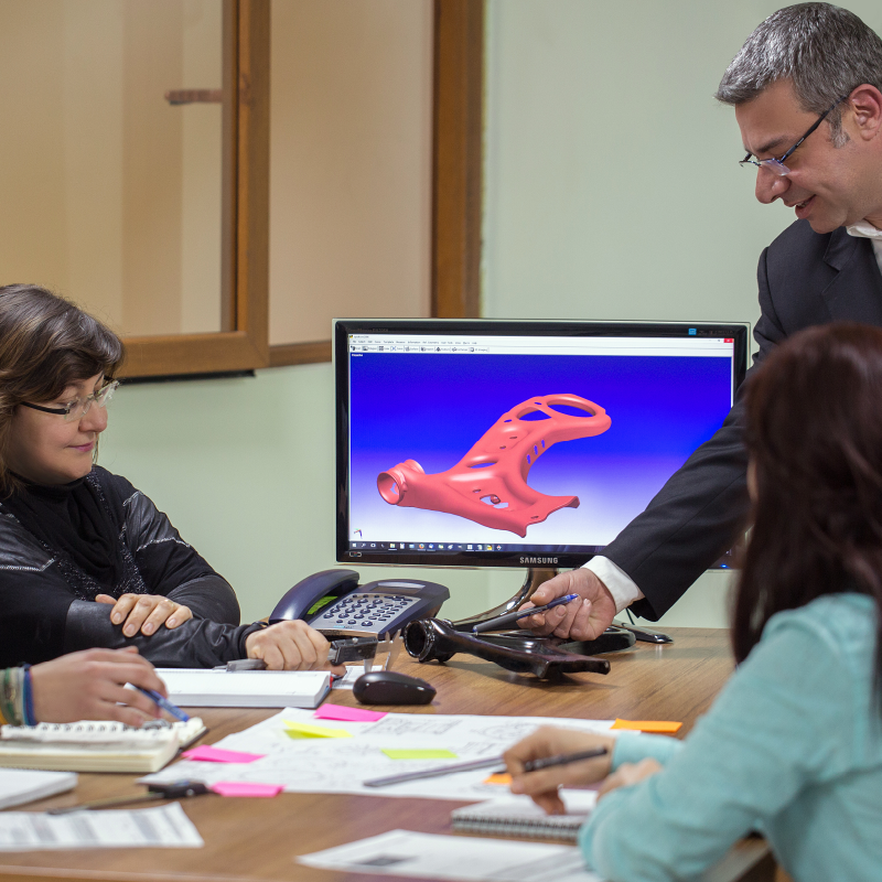
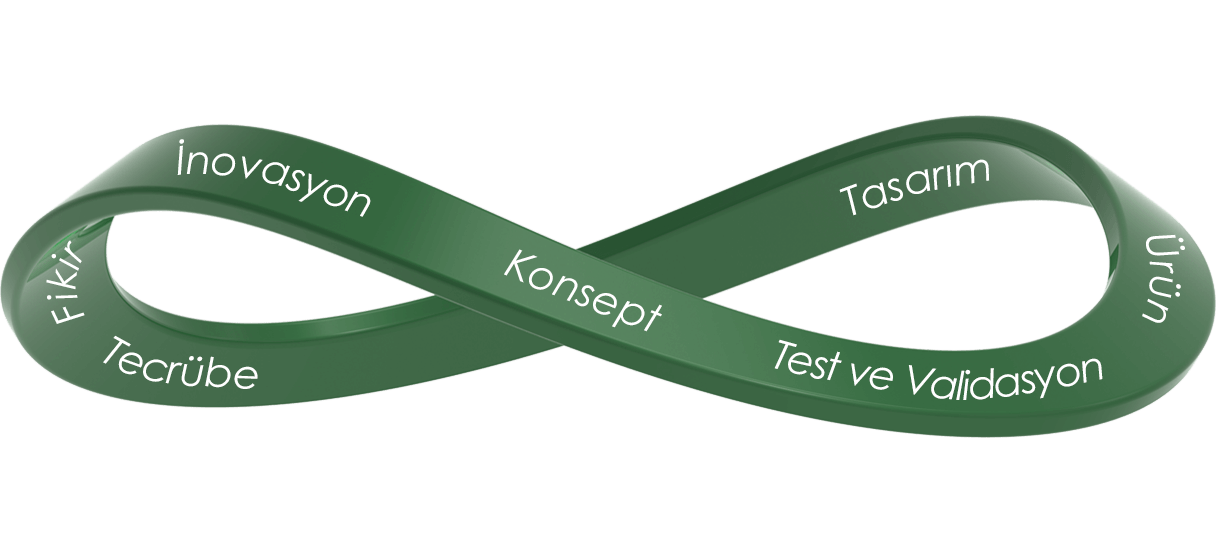
2005 yılından beri Ürün Tasarım ve Ürün Geliştirme çalışmalarımız ile farklı sektörlere yapılan binlerce projeden oluşan tecrübelerimiz yeni projelerde bize yaratıcı fikirler ve farklı yaklaşımlar ile ürünlere yenilikler katmaktayız. İnovasyon yöntemleri olan Triz ve 3P...
Yeni bir yaklaşım ile yapılacak olan Ürün tasarımı ve Ürün geliştirme projelerimizde müşterilerimiz ile beraber inovasyon methodolojisi uygulamaya başlanılmaktadır. Müşterilerimize proje başlangıcında yalın ve yaratıcılık methodolojisi danışmanlığı vererek ürünün daha yenilikçi, uzun ömürlü ve sürdürülebilir...
Ürün geliştirme var olan bir ürünün güncellenmesi, maliyetinin düşürülmesi, rekabet gücünün arttırılması, piyasa ömrünün uzatılması, kıyaslama esaslı kullanımı gibi benzeri amaçlar için tasarım ve üretim bazlı ürünün üzerinde yapılan geliştirme çalışmaları olarak tanımlamaktayız. Ürün geliştirme...

Ürün Tasarım stratejimiz çıkacak ürünün; Yüksek teknolojiye sahip olması, inovasyon katkısıyla yenilikçi ve yaratıcı fikirler ile donatılmış olması, düşük maliyetli yeni malzemeler ve üretim metotları ile yüksek kalitede üretilebilmesidir. Müşterilerin İstediklerini; teslim etmektir. Bu müşterilerimizin...
Bir ürünün piyasada benimsenmesi, sahiplenilmesi, müşteri tavsiye skoru NPS (Net Promoter Score) gibi temel metrikler söz konusu olduğunda, ürününüzün yüksek veya düşük performans gösterdiğini nasıl anlarsınız? Seçeneklerden biri, mevcut performansınızı geçmiş performansınızla karşılaştırmaktır. Bir diğeri,...
 |


27.01.2026
Endüstriyel ürün tasarımı; estetik kadar fonksiyon, sürdürülebilirlik ve rekabet avantajı üretme disiplinidir. Bu hedeflere ulaşmanın en etkili yollarından biri benchmark (kıyaslama) yaklaşımıdır. Benchmark yalnızca rakip ürünleri incelemekle sınırlı değildir; doğa, milyonlarca yıllık test süreciyle en...
30.11.2025
Benchmark’larınızın Gizli Kahramanı : Geriye Dönük Mühendislik “Rakibimiz bunu nasıl bu kadar iyi yapıyor? Bu soru, hemen her inovasyon ekibinin aşina olduğu bir iç ses. İşte tam bu noktada geriye dönük mühendislik, benchmark çalışmalarınızı sıradan...

29.11.2025
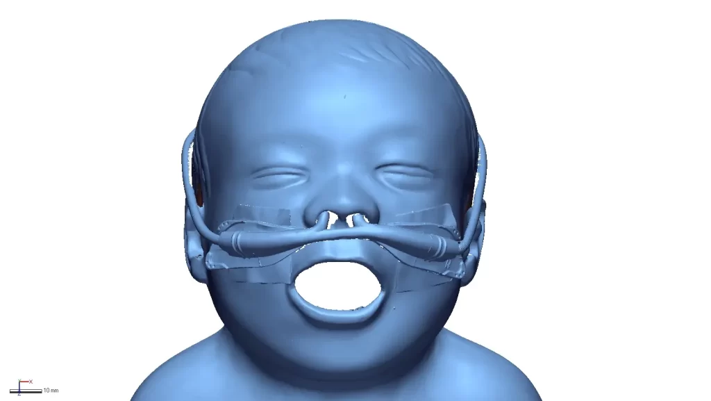
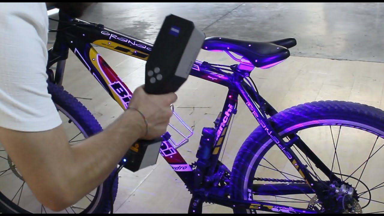
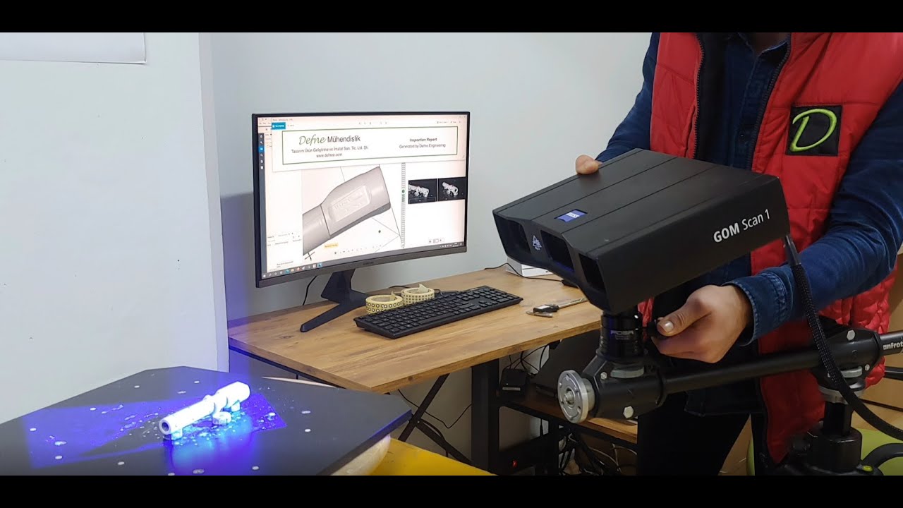
Defne Mühendislik, fotogrametri sistemleri, optik ve lazer tarama ekipmanları kullanır. Ayrıca, kendi geliştirdiği metod ve scriptler sayesinde her proje için hassasiyet ve detay standardını sağlamaktadır.
19.11.2025
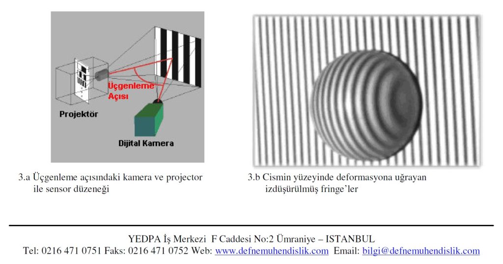
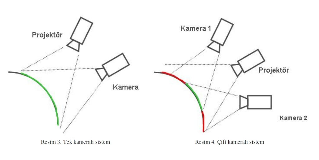
Optik Üçgenleme 3B tarama Fotoğraf, en geniş anlamı ile 3 boyutlu dünyayı 2 boyutlu resimlere dönüştürme işlemidir. Ne yazık ki bu dönüşüm işlemini tamamiyle yapmak olası değildir. Derinlik gibi bazı bilgilerin kaybolması söz konusudur. 3...
19.11.2025
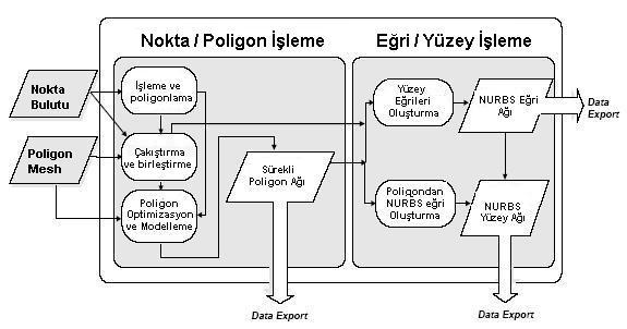
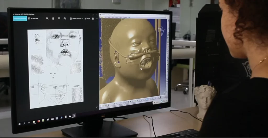
Geriye Dönük Mühendislik ve RapidFormAhmet ÇakırUzay MühendisiDefne Mühendislik Ltd. Sti Geriye Dönük – Tersine Mühendislik Nedir? Mühendislik, bir ürünün, sistemin veya bir yapının tasarımını, üretimini ve devamlılıgınısaglayan bir uzmanlık alanı ve iskoludur. Mühendisligi en genis...
08.11.2025
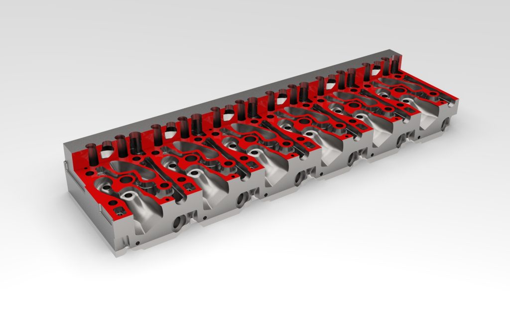
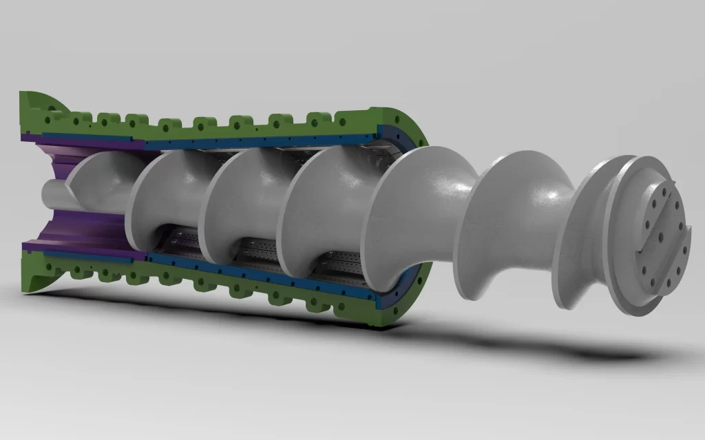
Tersine Mühendislik ve Ürün Geliştirme için Modern Teknolojilerin Gücü Modern endüstriyel süreçlerde, mevcut bir ürünün tasarımını ve işlevselliğini anlamak, iyileştirmek veya yeni bir versiyonunu oluşturmak için tersine mühendislik vazgeçilmez bir disiplin haline gelmiştir. Bu süreç,...
05.11.2025
Benchmark’larınızın Gizli Kahramanı : Geriye Dönük Mühendislik “Rakibimiz bunu nasıl bu kadar iyi yapıyor? Bu soru, hemen her inovasyon ekibinin aşina olduğu bir iç ses. İşte tam bu noktada geriye dönük mühendislik, benchmark çalışmalarınızı sıradan...
02.02.2024
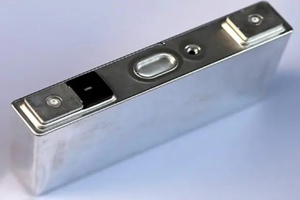
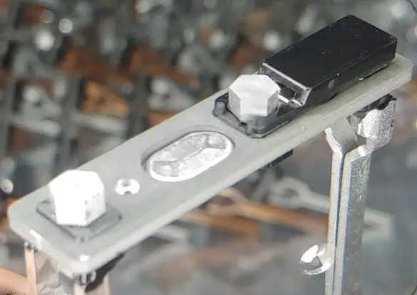
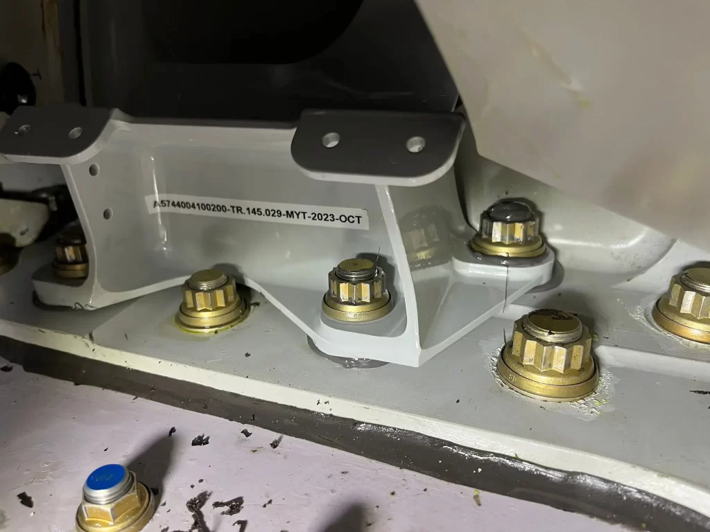
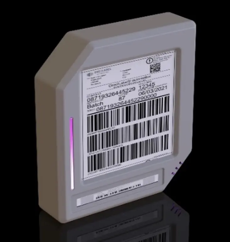
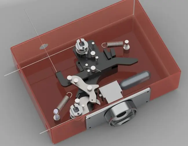
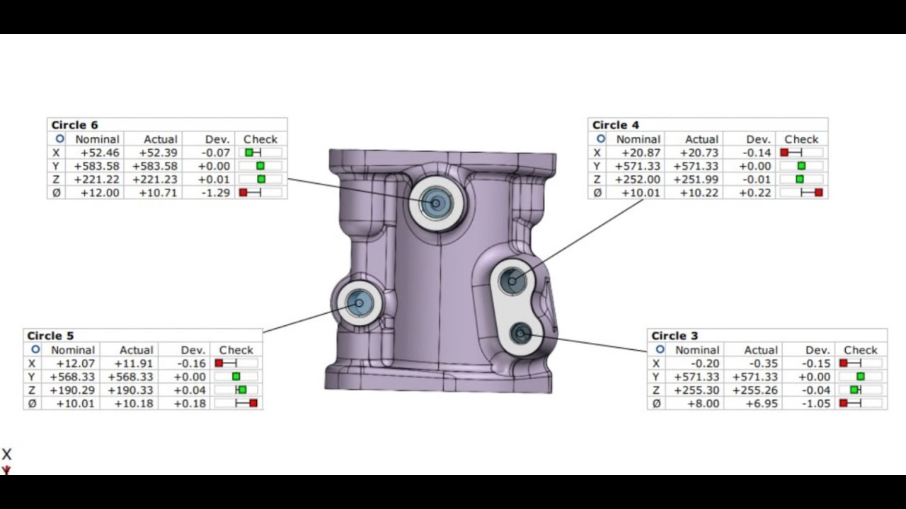
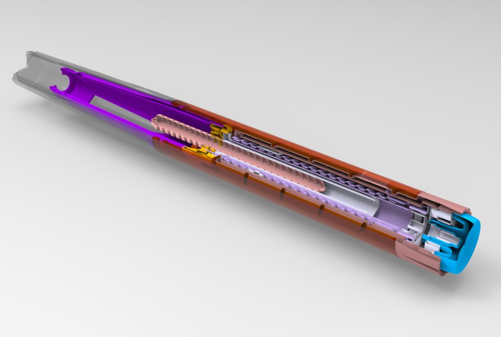
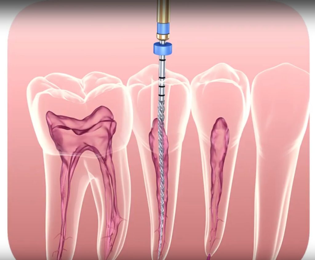
Tersine Mühendislik çalışmalarımızın temeli 3 boyutlu ölçüm verilerine dayanmaktadır. 3 boyutlu ölçüm ne kadar hassas ve detaylı ise yapılacak olan çalışmada o seviyede hassas ve detaylı olabilmektedir. Küçük ölçekli parçaların 3d ölçümleri konusunda özel bir...
12.01.2024
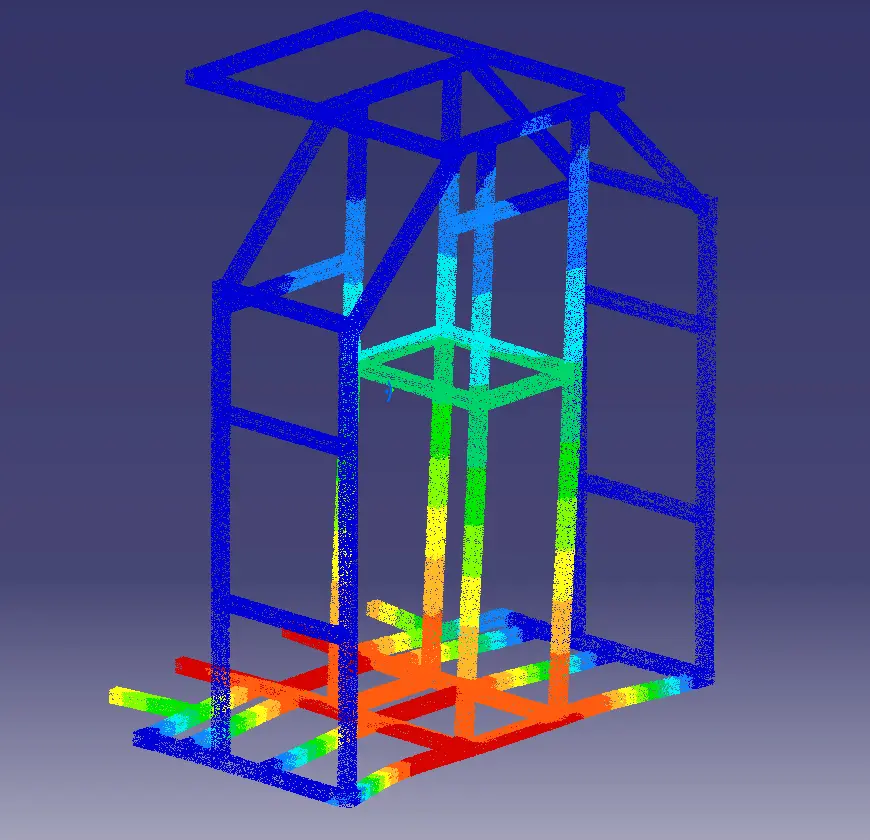
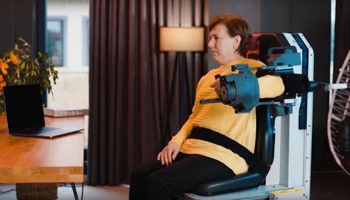
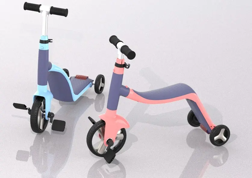
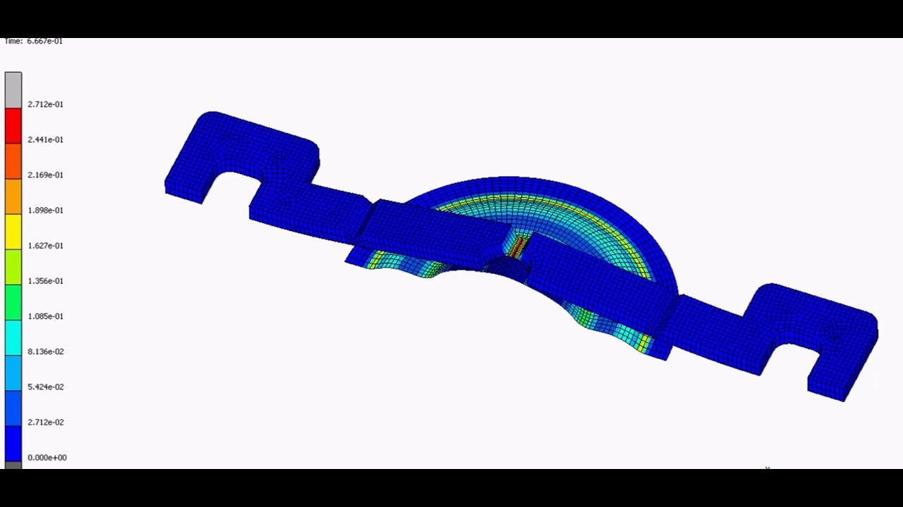
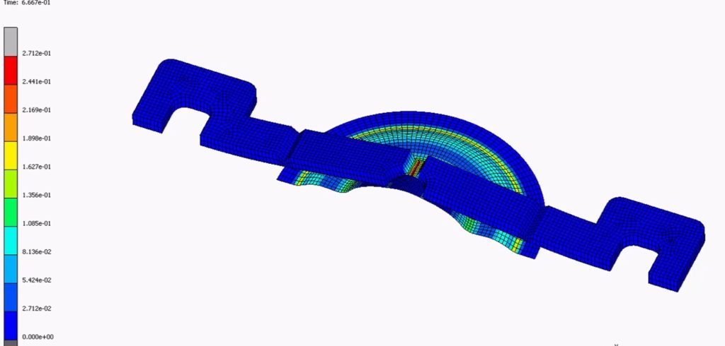
Ürün Tasarım ve Geliştirme projelerinde tasarımların onaylanması, doğrulanması, çalışma şartlarındaki fonksiyon testleri, davranışları, ergonomik uygunluklar gibi özellikler mock-up, prototip ve/veya bigisayar destekli yapısal analizler ile gerçekleştirmekteyiz.
29.12.2023
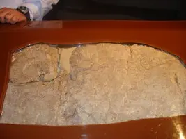
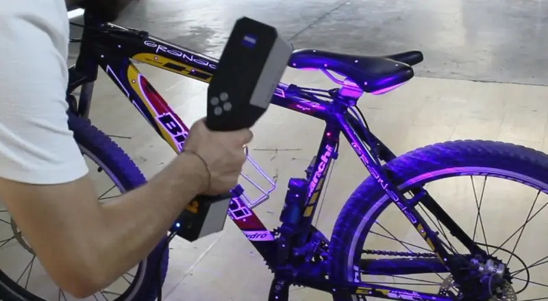
Tarama işlemlerinde ölçüm sonucunun en doğru şekilde elde edilebilmesi için oldukça hassas çalışılması gerekmektedir. 2005 yılından beri gerçekleştirdiğimiz 3 boyutlu ölçüm çalışmalarımızın sağladığı tecrübe ile hassas, mobil 3 boyutlu ölçüm çalışmalarımız için en doğru sistem...
28.12.2023
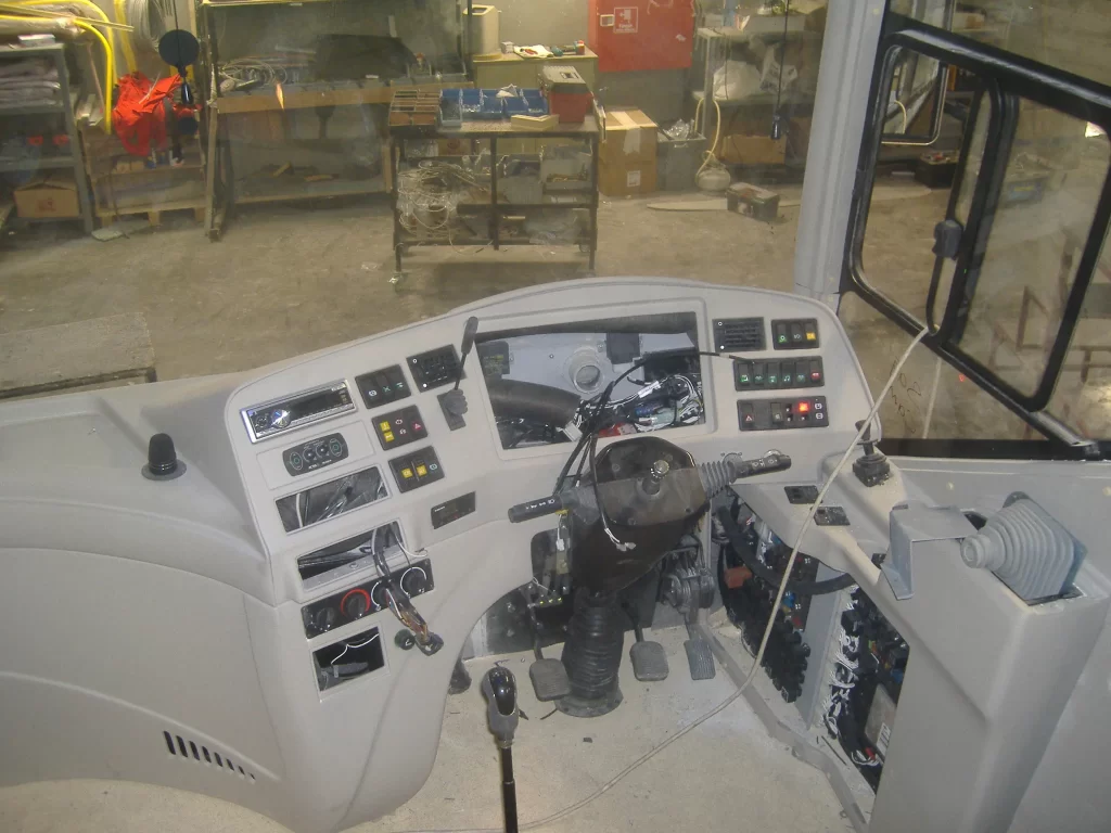
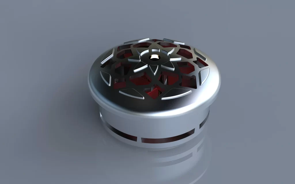
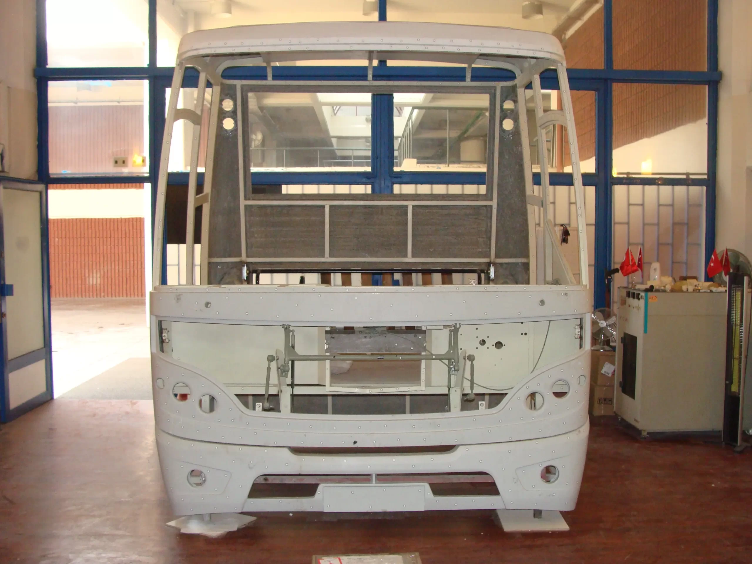
Defne Mühendislik, endüstriyel ürün tasarımı ve mühendislik geliştirme süreçlerinde konsept tasarım, mekanik tasarım, 3D modelleme, prototipleme, test-doğrulama ve seri üretim hazırlığını tek çatı altında sunar. Ürünler, kullanım alanına göre test edilir; bakım, servis, geri dönüşüm...
12. Otomotiv ve Üretim Teknolojileri Sempozyumu 13-14 Mayıs 2011
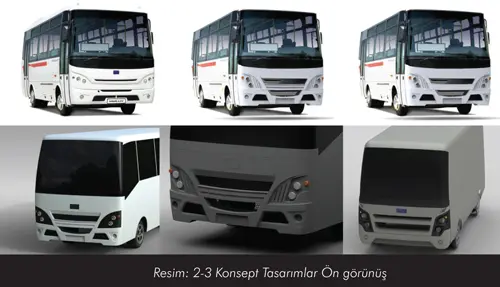
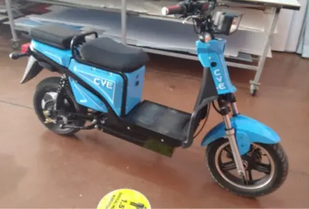
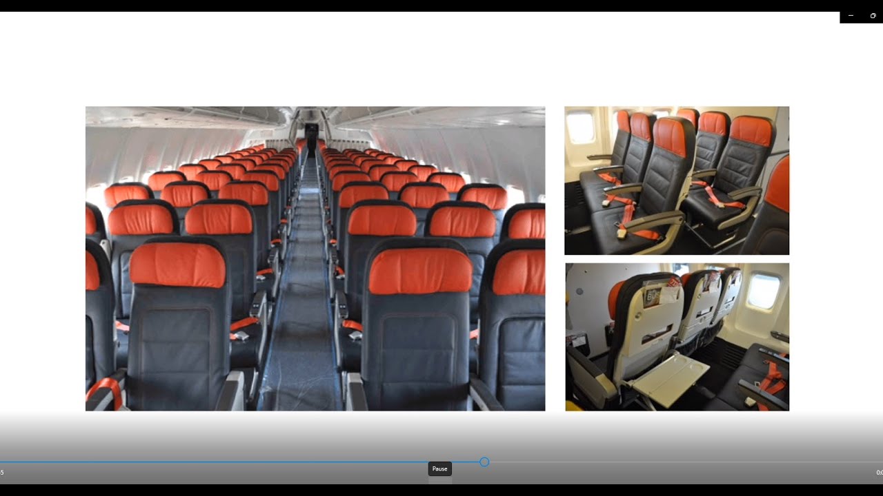
Yolcu Taşıma Araçları Tasarım ve Uygulama
TMMOB Makina Mühendisleri Odası
12. Otomotiv ve Üretim Teknolojileri Sempozyumu
Ayrıca TMMO yayınlarında :
TERSİNE MÜHENDİSLİK SÜRECİ ve UYGULAMALARI
makalemize ulaşabilirsiniz.


Müşteri Temsilcisi
1